Common DC Bus Systems How Shared DC Buses Improve Multi-Drive Applications
Learn how shared DC bus systems connect multiple Variable Frequency Drives, reuse regenerative energy, and support centralized power, braking, regeneration, and ride-through solutions.
In This Article
Use this guide to understand what a DC bus is, how shared DC bus systems work, and how Bonitron solutions support multi-drive applications.
Bonitron Products
These solutions are commonly used to supply, protect, isolate, and manage energy within common DC bus systems.
What Is a DC Bus?
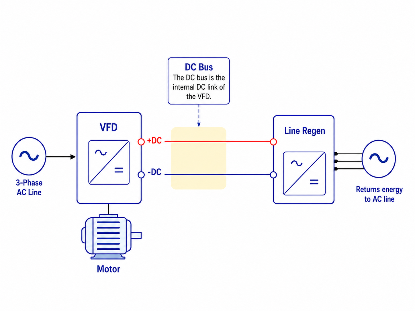
Inside most Variable Frequency Drives, incoming AC power is converted into DC power before being converted back into a controlled AC output for the motor. The internal electrical connection between the drive's rectifier and inverter is called the DC bus or DC link.
The DC bus typically includes capacitors that store and stabilize electrical energy. A standard VFD contains an input rectifier, a DC bus, and an inverter. Together, these sections convert incoming AC power into the controlled motor output required by the application.
The DC bus voltage must remain within the drive manufacturer's acceptable operating range. If the voltage falls too low, the drive may trip on undervoltage. If it rises too high, the drive may trip on overvoltage.
How a Shared DC Bus Works
A common DC bus, also called a shared DC bus, connects the DC bus terminals of multiple drives to one coordinated DC power system. Instead of each drive operating as a completely independent AC-to-DC-to-AC system, the connected drives can receive power from and exchange energy through the same DC link.
Consider a machine with two motors. Motor A is accelerating and consuming power while Motor B is decelerating and producing regenerative energy. In separate drive systems, Motor B's energy would normally be dissipated through a braking resistor or returned to the AC line. On a shared DC bus, some of that energy can flow to Motor A.
This transfer can reduce the amount of energy drawn from the incoming AC source and reduce the energy that must be converted into heat. If the regenerative energy exceeds what the other connected drives are consuming, the remaining energy must still be managed through dynamic braking, line regeneration, or energy storage.
Common DC Bus System Configurations
Drives With Individual AC Inputs
Multiple standard drives may retain their individual AC input connections while also being connected at their DC bus terminals. This arrangement can allow energy sharing, but the input rectifier bridges must be properly isolated to prevent circulating currents.
Centralized Common Bus Power Supply
One dedicated power supply can convert incoming AC power into DC power for multiple connected drives. The supply must be sized for the combined motoring load, overload requirements, operating sequence, total bus capacitance, and precharge demand.
Regenerative Common Bus Power Supply
A regenerative DC bus power supply supplies power during motoring and returns excess DC bus energy to the AC line during regenerative operation. This is useful in systems with frequent, extended, or high-energy braking cycles.
Shared Braking or Ride-Through Equipment
Several drives may share a properly sized braking transistor, resistor bank, line regeneration unit, or Uninterruptible Power for Drives system. The design must account for the maximum combined demand and the direction in which energy is allowed to flow.
Benefits of a Common DC Bus System
A shared DC bus can improve the way a multi-drive machine uses energy, manages regenerative events, and coordinates common power equipment.
Energy Sharing
Regenerative energy from one drive can support another drive that is motoring at the same time.
Reduced Resistor Demand
Energy reused by other drives does not need to be dissipated as heat through braking resistors.
Shared Equipment
Multiple drives may use one coordinated braking, regeneration, or ride-through system.
Centralized DC Power
A dedicated common bus supply can provide DC power to several drives from one source.
Reduced Duplication
A centralized architecture may reduce duplicated rectifiers, braking devices, and related components.
System Coordination
The power system can be designed around the combined operating profile of the entire machine.
Common DC Bus Engineering Review
A common DC bus requires more than connecting the positive and negative DC terminals of several drives. Engineers must document how each drive operates throughout the machine cycle and verify that the drives, conductors, protection, precharge system, and energy-management equipment are compatible.
Use the guide below to identify the main design questions that should be answered before selecting a common bus architecture.
| Operating Condition | Engineering Question | Possible Design Need |
|---|---|---|
| Several drives accelerate together | What is the combined peak motoring demand? | A larger common bus supply, adequate conductor sizing, or staged acceleration. |
| One drive brakes while another accelerates | Can the regenerative energy be reused? | A shared DC connection and the correct sharing diode arrangement. |
| All drives decelerate together | Where will the excess regenerative energy go? | Dynamic braking, line regeneration, or energy storage. |
| Drives retain separate AC inputs | Could their input bridges circulate current? | Common bus sharing diodes or another approved isolation method. |
| Multiple drives require ride-through | Should the drives share backup power only or also exchange energy? | A UPD system with sharing or isolation diodes. |
| Large total bus capacitance | How will inrush current be limited? | A precharge circuit sized for the total connected capacitance. |
| A drive branch develops a fault | Can the branch be safely isolated? | DC-rated fusing and coordinated disconnect protection. |
| Frequent regeneration occurs | Is resistor heat and energy loss acceptable? | A regenerative DC bus power supply or line regeneration system. |
Bonitron Engineering Note
As a general rule, the nominal DC bus voltage of a standard three-phase drive is approximately 1.35 times the AC line-to-line voltage under normal loaded operating conditions. Under unloaded or lightly loaded conditions, the DC bus voltage is approximately 1.414 times the AC line-to-line voltage.
How Regenerative Energy Is Managed
Internal Energy Sharing
When one drive regenerates while another drive is consuming power, the energy can be reused within the common bus before another energy-management method is required.
Dynamic Braking
A braking transistor and resistor convert excess electrical energy into heat when the common bus voltage reaches the braking threshold.
Line Regeneration
A line regeneration system returns excess DC bus energy to the incoming AC source instead of dissipating it as heat.
Energy Storage and Ride-Through
Capacitors, ultracapacitors, batteries, or a Bonitron UPD system can support the DC bus during a voltage sag or outage and may absorb or supply energy depending on the system architecture.
How Bonitron Works Within Common DC Bus Systems
Supplying the DC Bus
Bonitron common bus power supplies convert incoming AC power into DC power for one or multiple drives. The M3712 can power one or more three-phase drives from a single-phase source through their DC bus terminals, while the M3713 provides three-phase common bus power for multi-drive systems.
Controlling Energy Flow
Bonitron sharing and isolation diode assemblies control how current moves between drives, AC input bridges, and shared DC sources. Sharing diodes support controlled bidirectional energy exchange, while isolation diodes provide one-way power flow.
Managing Excess Regenerative Energy
The M3545P and M3645P operate as regenerative DC bus power supplies. They supply DC power during motoring and return excess regenerative energy to the AC line when the bus voltage rises.
Protecting and Completing the System
Bonitron also supplies AC and DC fuse plates, precharge solutions, braking transistors, braking resistors, line regeneration modules, and ride-through equipment used to complete a coordinated common bus system.
Applications That Use Common DC Bus Systems
Shared DC buses are most useful where multiple drives operate as part of one machine and their motoring and regenerative cycles can be coordinated.
Automated Machinery
Regenerative energy from one axis can support another axis that is accelerating.
Cranes and Hoists
Lowering loads generate energy that may be shared, dissipated, or returned to the AC line.
Material Handling
Conveyors, palletizers, and storage systems often contain coordinated drives with overlapping cycles.
Centrifuges
Stored rotational energy can produce significant regenerative power during deceleration.
Dynamometers
Energy can circulate between a motoring drive and an absorbing or regenerating drive.
Printing and Packaging
Multiple driven rolls accelerate, tension, and decelerate in coordination.
Elevators
Travel direction, load, and counterweight balance create alternating motoring and overhauling conditions.
Frequently Asked Questions
What is the difference between a DC bus and a common DC bus?
A DC bus is the internal DC power link within one drive. A common DC bus connects the DC links of multiple drives or supplies several drives from one centralized DC source.
Can any VFD be connected to a common DC bus?
No. The drive must have accessible DC bus terminals and must be approved by its manufacturer for the intended configuration. Engineers must also verify voltage compatibility, precharge, grounding, fusing, and rectifier isolation.
Does a common DC bus save energy?
It can. When regenerative and motoring cycles overlap, energy produced by one drive can be reused by another instead of being dissipated through a resistor.
Does a common DC bus eliminate the need for braking resistors?
Not necessarily. If regenerative energy exceeds the power being consumed by the connected drives, the bus still requires dynamic braking, line regeneration, or energy storage.
Why are common bus diodes needed?
Diodes control current direction and help prevent unintended circulating currents. Sharing diodes permit controlled energy exchange, while isolation diodes provide one-way power flow.
Can multiple drives share one regeneration or UPD system?
Yes, when the common bus, diodes, protection, and shared equipment are properly designed and sized for the combined system demand.