VFD Overvoltage Faults Causes, Symptoms & Prevention
Learn why Variable Frequency Drives experience overvoltage faults, what regenerative energy is, and the best methods engineers use to eliminate nuisance trips.
In This Article
Use this guide to understand what causes VFD overvoltage faults, how to recognize symptoms, and which solution path may fit the application.
Bonitron Products
These solutions are commonly used to manage regenerative energy and reduce nuisance overvoltage trips.
What is VFD Overvoltage?
Variable Frequency Drives (VFDs) are widely used throughout industry to control motor speed, improve efficiency, and optimize process control. Despite their reliability, one of the most common issues engineers encounter is a VFD overvoltage fault.
Inside every VFD is a DC bus that stores electrical energy. During normal operation, incoming AC power is converted into DC power and then back into a controlled AC output for the motor.
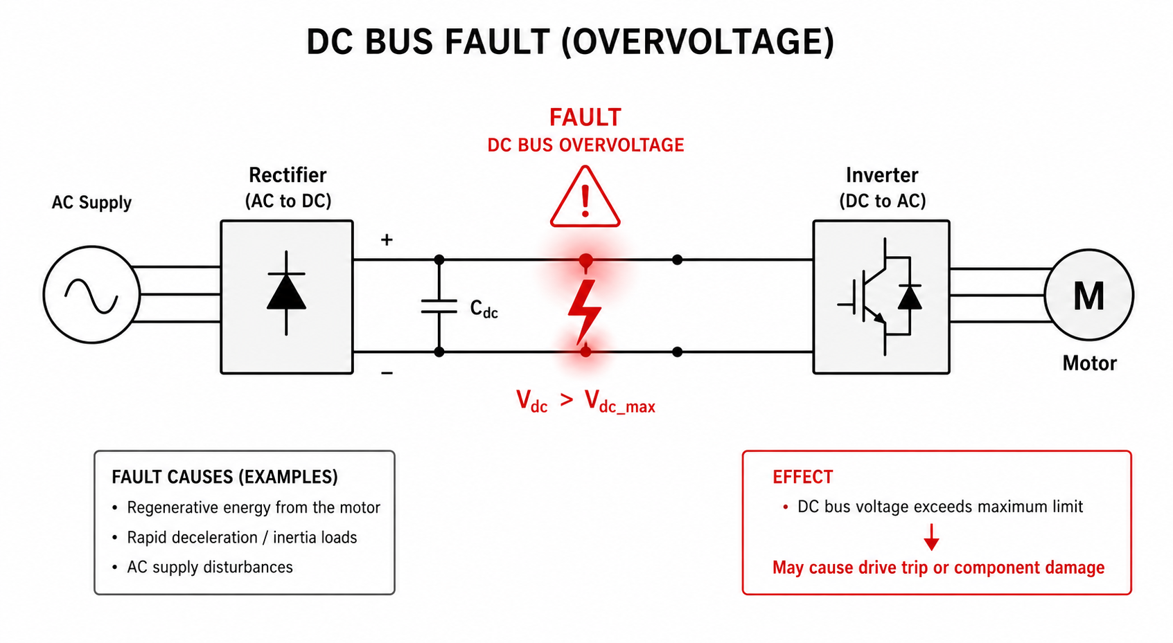
When the voltage on the DC bus exceeds the drive's safe operating limits, the VFD generates an overvoltage fault and shuts down to protect itself from damage.
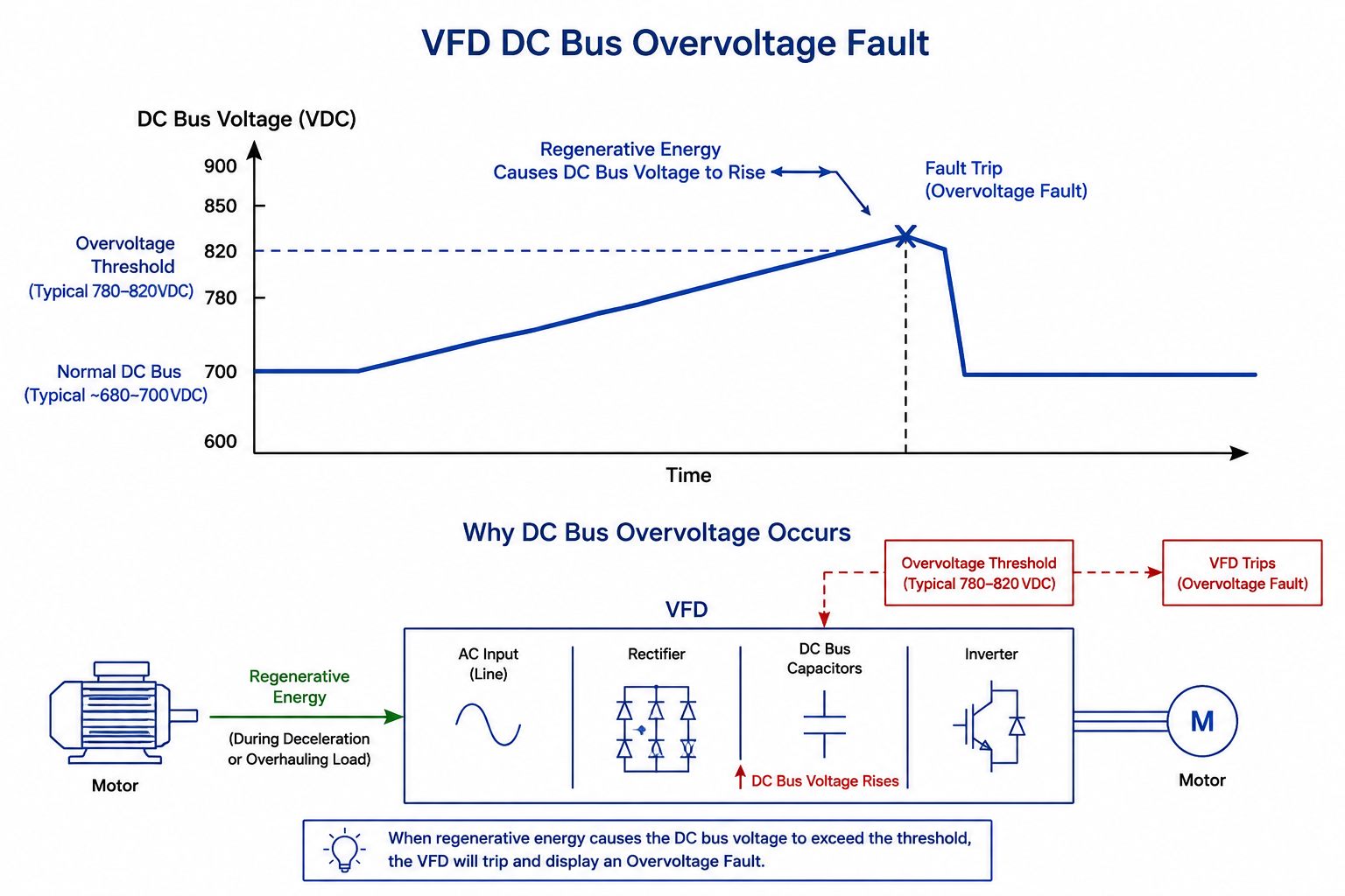
In many applications, this occurs because the motor begins acting as a generator and returns energy back into the drive. If that energy cannot be safely dissipated or redirected, DC bus voltage rises until the drive trips.
How VFD Overvoltage Happens
A VFD overvoltage fault occurs when the DC bus voltage rises above the drive’s safe operating threshold. In many applications, this happens when the motor is being driven by the load instead of driving the load. This condition is common during fast deceleration, lowering loads, stopping high-inertia equipment, or managing regenerative energy from overhauling loads. When the motor regenerates energy back into the drive, that energy charges the DC bus capacitors. If the drive cannot dissipate, share, or return that energy fast enough, the DC bus voltage rises and the drive trips on an overvoltage fault. Common examples include cranes, hoists, elevators, centrifuges, conveyors, test stands, and other systems with frequent starts, stops, or descending loads.
Common Causes of VFD Overvoltage Faults
Rapid Deceleration
One of the most common causes of overvoltage faults is commanding a motor to stop too quickly. The faster a motor decelerates, the more regenerative energy is generated.
Overhauling Loads
Applications involving gravity-driven loads naturally create regenerative energy. Examples include cranes, elevators, hoists, mining conveyors, and oil & gas drawworks systems.
Improper Braking Resistor Sizing
If a braking resistor is undersized or damaged, it may be unable to dissipate excess energy effectively, allowing DC bus voltage to rise.
Common DC Bus Systems
Multiple drives sharing a common DC bus require proper energy management. Excess regenerative energy can result in bus overvoltage if not properly controlled.
Symptoms of an Overvoltage Problem
VFD overvoltage issues often appear during specific operating conditions. The timing of the fault can help narrow down whether the problem is related to deceleration, regenerative energy, load behavior, or braking equipment.
Trips During Deceleration
The drive faults when the motor is commanded to stop faster than the load can safely release energy.
Faults While Lowering Loads
Gravity-driven or overhauling loads can force the motor to regenerate energy back into the DC bus.
Unexpected Downtime
Repeated trips can interrupt production and require drive resets before the machine can continue operating.
Repeated Fault Codes
The same overvoltage fault may return after reset if the root cause has not been corrected.
Intermittent Shutdowns
Faults may only appear during heavy loads, fast stops, or specific parts of the machine cycle.
Braking Equipment Stress
Overheated or undersized braking resistors can indicate that the application needs a better energy management path.
How to Diagnose a VFD Overvoltage Fault
The timing of a VFD overvoltage fault can help identify whether the issue is caused by deceleration, regenerative energy, incoming power, braking equipment, or the overall drive system design. Instead of only resetting the drive, document when the fault occurs and what the machine is doing at the time of the trip.
Use the guide below to narrow down the likely cause and determine whether the application may require drive parameter adjustments, braking equipment, line regeneration, or a more complete review of the DC bus system.
| When the Fault Happens | Likely Cause | What to Check | Possible Solution Path |
|---|---|---|---|
| During deceleration | Regenerative energy from the motor is charging the DC bus faster than the drive can manage it. | Review deceleration time, load inertia, stopping frequency, and DC bus voltage during the stop. | Increase deceleration time or add dynamic braking to dissipate excess regenerative energy. |
| While lowering a load | An overhauling load is driving the motor and sending energy back into the drive. | Check the load profile, lowering cycle, braking demand, duty cycle, and whether the load is pulling the motor faster than commanded. | Use a braking resistor, braking transistor, or line regeneration solution depending on the application duty cycle. |
| At startup | Incoming line voltage, drive settings, or stored DC bus energy may be outside the expected range. | Verify input voltage, drive parameters, recent fault history, and power quality conditions. | Correct line voltage issues, review drive setup, and inspect the application for power quality concerns. |
| While running steady | Line disturbances, shared bus conditions, or unexpected regenerative events may be raising the DC bus voltage. | Check incoming power, DC bus voltage, common bus configuration, and nearby equipment cycling on the same power system. | Review power quality, DC bus design, and whether braking or regeneration equipment is needed. |
| When the braking resistor overheats | The resistor may be undersized, damaged, misapplied, or operating beyond its duty cycle rating. | Check resistance value, wattage rating, duty cycle, enclosure temperature, airflow, and resistor wiring. | review the application for a more suitable braking or regeneration solution. |
| Faults repeat after reset | The root cause has not been corrected, so the DC bus continues to exceed the drive limit. | Document when the fault occurs, the load condition, drive fault logs, motor data, voltage, horsepower, and operating cycle. | Review the full application profile and evaluate dynamic braking, line regeneration, or system-level DC bus management. |
Bonitron Engineering Note
A longer deceleration time may reduce overvoltage faults, but it is not always acceptable in production environments. Applications with frequent stops, high-inertia loads, lowering loads, or repeated regenerative events may require a properly sized braking resistor, braking transistor, line regeneration solution, or common DC bus review.
How Can VFD Overvoltage Be Prevented?
Increase Deceleration Time
Increasing stop times reduces regenerative energy and often eliminates nuisance trips.
Install Dynamic Braking
Dynamic braking systems use braking transistors and resistors to convert excess electrical energy into heat.
Implement Line Regeneration
Line regeneration systems return DC energy back to the utility AC line rather than wasting it as heat.
Use Proper System Design
Proper resistor sizing, DC bus design, and application-specific energy management can significantly improve system reliability.
Applications Commonly Affected
VFD overvoltage faults are common in applications where the motor may be driven by the load, where equipment stops quickly, or where high-inertia systems return energy back into the drive.
Cranes and Hoists
Lowering loads can create regenerative energy that raises DC bus voltage.
Mining Conveyors
Inclined or overhauling conveyor sections can push energy back into the drive system.
Material Handling
Frequent starts, stops, and load changes can create repeated braking demand.
Oil and Gas Drawworks
Lowering and high-energy motion profiles often require controlled regenerative energy management.
Industrial Fans
Rapid deceleration or back-driven airflow can create overvoltage conditions in some fan systems.
Centrifuges
High-inertia loads can regenerate significant energy during deceleration.
Elevators
Descending or counterweighted motion can create overhauling load conditions.
Frequently Asked Questions
What causes a VFD overvoltage fault?
The most common causes are regenerative energy, rapid deceleration, overhauling loads, and improper braking resistor sizing.
What is regenerative energy?
Regenerative energy occurs when a motor acts as a generator and returns power back into the drive.
Can a braking resistor prevent overvoltage faults?
Yes. Properly sized braking resistors are one of the most common solutions for managing regenerative energy.
When should line regeneration be considered?
Line regeneration is often preferred when energy savings, reduced heat generation, and continuous regenerative operation are important.